CHAPTER IIIofPRACTICAL MECHANICS FOR BOYS
|
Some simple directions in the holding and setting of tools may be of service to the novice. Practice has shown the most effective way of treating different materials, so that the tools will do the most efficient work.
A tool ground in a certain way and set at a particular angle might do the work admirably on a piece of steel, but would not possibly work on aluminum or brass.
Lathe Speed.—If the lathe should run at the same speed on a piece of cast iron as with a brass casting, the result would not be very satisfactory, either with the tool or on the work itself.
Some compositions of metal require a high speed, and some a hooked tool. These are things which each must determine as the articles come to the shop; but there are certain well-defined rules with respect to the ordinary metals that should be observed.
The Hack Saw.—Our first observation should be directed to the hand tools. The hack saw is one of the most difficult tools for the machinist to handle, for the following reasons:
First, of the desire to force the blade through the work. The blade is a frail instrument, and when too great a pressure is exerted it bends, and as a result a breakage follows. To enable it to do the work properly, it must be made of the hardest steel. It is, in consequence, easily fractured.
Second. The novice will make short hacking cuts. This causes the teeth to stick, the saw bends, and a new blade is required. Take a long sweeping cut, using the entire length of the blade. Do not oscillate the blade as you push it through the work, but keep the tooth line horizontal from one end of the stroke to the other. The moment it begins to waver, the teeth will catch on the metal on the side nearest to you, and it will snap,
Third. The handle is held too loosely. The handle must be firmly held with the right hand, and the other held by the fingers lightly, but in such a position that a steady downward pressure can be maintained. If loosely held, the saw is bound to sag from side to side during the stroke, and a short stroke accentuates the lateral movement. A long stroke avoids this.
The hack saw is one of the tools which should be used with the utmost deliberation, combined with a rigid grasp of the handle.
Files.—For remarks on this tool see Chapter IV, which treats of the subject specially.
Grindstones, Emery and Grinding Wheels.—A good workman is always reflected by his grinding apparatus. This is true whether it has reference to a grindstone, emery, corundum wheel, or a plain oil stone. Nothing is more destructive of good tools than a grooved, uneven, or wabbly stone. It is only little less than a crime for a workman to hold a tool on a revolving stone at one spot.
Carelessness in Holding Tools.—The boy must learn that such a habit actually prevents the proper grinding, not only of the tool he has on the stone, but also of the one which follows. While it is true that all artificially made grinders will wear unevenly, even when used with the utmost care, due to uneven texture of the materials in the stone, still, the careless use of the tool, while in the act of grinding, only aggravates the trouble.
Another fault of the careless workman is, to press the bit against the stone too hard. This cuts the stone more than it wears off the tool, and it is entirely unnecessary. Furthermore, it heats up the tool, which should be avoided.
Calipers.—A true workman, who endeavors to turn out accurate work, and preserve his tools, will never test the work with his calipers while the piece is turning in the lathe. A revolving cast iron disk will cut ruby, the hardest substance next to the diamond, so it is not the hardness of the material which resists wear, but the conditions under which it is used.
Care in Use of Calipers.—The calipers may be of the most hardened steel, and the work turned up of the softest brass, the latter, when revolving, will grind off the point of the tool, for the reason that the revolving piece constantly presents a new surface to the point of the calipers, and when tests are frequently made, it does not take long to change the caliper span so that it must be reset.
As stated elsewhere, the whole energy of the lathe is concentrated on the bit or cutting tool, hence, in order to get the most effective work out of it requires care; first, in grinding; and, second, in setting.
Machine Bits.—It does not always matter so much whether you use a square, pointed, or a round-nosed bit, provided it is properly ground and set in the tool holder. As a rule, the more brittle the metal the less the top rake or angle should be.
In the chapter relating to the grinding of tools, references were made as to the most serviceable bits for the various metals. We are concerned here with the setting or holding of these articles.
 |
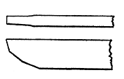 |
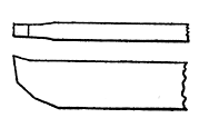
| Fig. 30. Plain Hook Tool | Fig. 31. Plain Straight Tool |
The two illustrations here given show a pair of plain bits, in which Fig. 30 represents a hook-shaped formation, and Fig. 31 a straight grind, without any top rake. The hooked bit would do for aluminum, or steel, but for cast iron the form shown in Fig. 31 would be most serviceable.
Then the side bits, such as the round-nosed, Fig. 32 and the square end, Fig. 33, may be ground hooked, or with a top rake, or left flat.
The too common mistake is to grind the lower or clearance side at too great an angle. Fig. 34 shows the correct angle, and the dotted line A illustrates the common tendency to grind the clearance.
The Proper Angle for Lathe Tools.—Now there is a reason why the angle of from 10 to 15 should be maintained in the clearance. The point of the tool must have suitable support for the work it is required to do, so it will not chatter or yield in the slightest degree. A bit ground along the dotted line has a cutting edge which will spring down, and consequently break or produce a rough surface.
Then, again, the angle of the clearance acts as a guide, or rather, a guard, to prevent the tool from going in too far, as will now be explained.
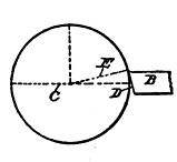
Setting the Bit.—In order to understand the correct setting, examine the work A, in Fig. 35.
A is a cylinder being turned up in the lathe, and B the cutting tool, which approaches it on a horizontal line, C, extending out from the center of the cylinder A. This setting is theoretically correct, and in practice has been found most advantageous.
In this case let us assume that the clearance angle D is 15 degrees, as well as in the following figures.
Suppose we have a piece of tough steel, and the tool holder is raised so that the point of the tool is at the 15 degree line E, as shown in Fig. 36, in which case the clearance line D is at right angles to the line E. The line E is 15 degrees above the center line C.
The Setting Angle.—Now, it is obvious that if the tool should be raised higher than the line E it would run out of work, because the clearance surface of the tool would ride up over the surface cut by the edge of the tool.
If, on the other hand, the tool should be placed lower, toward the line C, the tendency would be to draw in the tool toward the center of the work A
In Fig. 37 the tool has its point elevated, in which case it must be lowered so the point will touch the work nearer the center line C.
The foregoing arrangement of the tools will be found to be effective where the material is soft and not too tough as with aluminum.
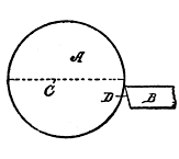
Bad Practice.—Figs. 38 and 39 show illustrations of bad practice which should never be resorted to. Fig. 38 shows the tool, held in a horizontal position, but with its point below the center line C. With any rough metal the tool could not possibly work, except to act as a scraper, and if it should be used in that position on cast iron, the tool itself would soon be useless.
 |
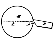 |
| Fig. 36. Correct Angle | Fig. 37. Wrong Angle |
Fig. 39 is still worse, and is of no value for any purpose except in polishing brass, where it would be serviceable. It would make a sorry looking job with aluminum. Brass requires a tool with very little top rake, and the point should be set near the center line C.
Lathe Speed.—It is often a question at what speeds to run the lathe for different work. If you know the speeds of your lathe at low and high gear, you must also consider the diameter of the work at the cutting point.
The rule is to have the bit cut from 15 to 20 feet per minute for wrought iron; from 11 to 18 feet for steel; from 25 to 50 for brass; and from 40 to 50 for aluminum.
 |
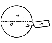 |
| Fig. 38. Too Low | Fig. 39. Improper Set |
As a result, therefore, if, at low speed, a piece 10 inches in diameter, runs at the proper speed to cut at that distance from the center, it is obvious that a piece 5 inches in diameter should ran twice as fast. This is a matter which time and practice will enable you to judge with a fair degree of accuracy
Observe this as a maxim: "Slow speed, and quick feed."
Boring Tools on Lathe.—The lathe is a most useful tool for boring purposes, better for some work than the drilling machine itself. The work which can be done better on a lathe than on a drilling machine, may be classified as follows:
1. When straight and true holes are required.
2. In long work, where the lathe is used to turn up the article, and where the drilling can be done at the same time.
3. Anything that can be chucked in a lathe.
4. Where the work is long and cannot be fixed in a drilling machine. The long bed of the lathe gives room for holding such work.
 |
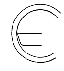 |
| Fig. 40. Internal Set | Fig. 41. Set for Brass |
The Rake of the Drill.—A boring tool requires some knowledge in setting. It should have a greater top rake than for the outside work, and the cutting edge should also be keener, as a rule.
In this class of work the material bored must be understood, as well as in doing outside work.
The hooked tool, Fig. 40, is shown to be considerably above the center line, and at that point it will do the most effective cutting on steel. If, on the other hand, brass is operated on there should be no top rake, as illustrated in Fig. 41, thus assuring a smooth job.
Laps.—This is a tool which is very useful, particularly for grinding and truing up the cylinders of internal combustion engines, as well as for all kinds of bores of refractory material which cannot be handled with the cutting tool of the lathe.
It is made up of a mandrel or rod of copper, with lead cast about it, and then turned up true, so that it is but the merest trifle larger than the hole it is to true up.
Using the Lap.—The roller thus made is turned rapidly in a lathe, and the cylinder to be trued is brought up to it and the roller supplied freely with emery powder and oil. As rapidly as possible the cylinder is worked over on the roller, without forcing it, and also turned, so as to prevent even the weight from grinding it unduly on one side.
More or less of the emery will embed itself in the lead, and thus act as an abrasive. The process is called "lapping."
Surface Gages.—Frequently, in laying out, it is necessary to scribe lines at a given distance from some part of the work; or, the conditions are such that a rule, a caliper, or dividers will not permit accurate measurement to be made.
For such purposes, what is called a surface gage was devised. This is merely a heavy base, provided with a pivoted upright on which is mounted a scribe that is held by a clamp so it may be turned to any angle.
Surface Gage.—The clamp holding the scriber is vertically movable on the pivoted upright. By resting the base of the surface gage on the line to be measured from, and swinging one point of the scriber to the place where the work is to be done, accuracy is assured. One end of the scriber is bent, so it can be adapted to enter recesses, or such places as could not be reached by the straight end.
To Chapter IV - On the First Use of the File
To Table of Contents and Glossary